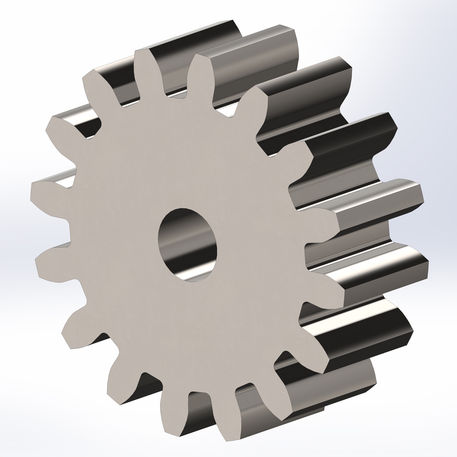
Solidworks drawing differential gear tutorial mechanical engineering box projects sketch cad 2d simple 3d solid works designer tutorials create train
Table of Contents
Table of Contents
If you’re interested in creating precise mechanical designs, drawing gears in SolidWorks is an essential skill. With this sophisticated software suite, you can create three-dimensional models and simulations of everything from simple gears to complex machinery. Whether you’re a professional design engineer or an amateur hobbyist, SolidWorks makes it easy to design and test gears that are 100% precise.
Designing gears in SolidWorks can present some challenges, particularly if you’re new to the software or to mechanical design in general. For example, the software includes many tools and features that can be overwhelming at first glance, and making sure your designs are accurate and error-free can be time-consuming. However, by learning just a few basic principles, you can create gears that are perfectly suited to your needs.
When you’re ready to start designing your gear in SolidWorks, the first step is to create a sketch of the gear’s cross-section. You can then use this sketch to generate the gear’s teeth and surrounding geometry, taking factors such as module, pitch, pressure angle, and helix angle into account. By using the software’s built-in toolbox and other features, you can create complex gears with a high degree of accuracy in just a few steps.
In summary, there are some key steps to follow when designing gears in SolidWorks, including creating a gear cross-section sketch, generating the gear’s teeth and geometry, and ensuring that the design is accurate and error-free. By taking the time to learn these basics, you can create gears that are perfectly suited to your needs.
How to Create a Gear Cross-Section Sketch in SolidWorks
When I first started designing gears in SolidWorks, I found it challenging to create a gear cross-section sketch that accurately reflected the gear’s intended shape. One of the most helpful things I learned was to create a sketch using a frontal view of the gear. This allowed me to generate the tooth profiles more easily, and to take into account factors such as module and pitch.
To create the sketch, start by opening a new sketch and selecting “Front Plane” or “Top Plane” as your reference plane. Depending on your design, you may need to adjust your view settings to get the best angle. Once you’ve selected your reference plane, you can use standard drawing tools like lines, circles, and arcs to create the cross-section of your gear.
One critical thing to keep in mind is that the dimensions and angles of the cross-section need to correspond to the gear’s intended specifications. You can use the “Smart Dimension” tool to check the distance between each pair of teeth, as well as the angle between the teeth and the gear’s central axis. Once you’ve created the cross-section, you can apply SolidWorks’ “Gear” feature to generate the teeth and related geometry.
Tips for Generating Accurate Gear Teeth in SolidWorks
Generating accurate gear teeth in SolidWorks can be challenging, particularly if you’re working with complex designs or require a high level of precision. However, by following a few best practices, you can streamline the process and create perfectly accurate gears every time.
One tip is to use SolidWorks’ “Gear” feature, which includes a range of settings for defining the gear’s module, pressure angle, and other key features. By selecting the appropriate settings for your design, you can rest assured that your gear’s teeth will be perfectly matched to your specifications. Additionally, when generating gear teeth, make use of SolidWorks’ mirroring functionality to avoid drawing each tooth individually and save valuable time.
How to Test Gear Functionality in SolidWorks
Once you’ve created a gear design in SolidWorks, it’s essential to test it to ensure that it functions as intended. SolidWorks makes it easy to simulate gear motion and performance using its built-in simulation tools. By applying various constraints and loads to your gear model, you can simulate its behavior under a range of circumstances and identify potential issues before you start the manufacturing process.
How to Troubleshoot Common Gear Design Issues in SolidWorks
Even when you’ve followed best practices for designing and testing gears in SolidWorks, you may encounter issues that require troubleshooting. One common mistake is incorrectly defining the gear module, which can cause the gear to be smaller or larger than desired. Additionally, if your gear is designed to mesh with another gear, make sure that the gears’ teeth are precisely aligned and that the gear’s pitch diameter matches the other gear’s pitch diameter.
Conclusion of How to Draw Gear in SolidWorks
Designing gears in SolidWorks requires precision, focus, and skill. By following the key steps outlined above and using SolidWorks’ powerful functionality to your advantage, you can create gears that are perfectly tailored to your needs. Whether you’re designing gears for mechanical systems, toys, or any other purpose, SolidWorks provides the tools and resources you need to succeed.
Questions and Answers
Q: What are the most critical factors to consider when designing gears in SolidWorks?
A: When designing gears in SolidWorks, it’s essential to consider factors such as module, pitch, pressure angle, and helix angle. By selecting the appropriate values for each of these parameters, you can ensure that your gear functions optimally and meets your specific needs.
Q: How can I ensure that my SolidWorks gear design is accurate?
A: To ensure the accuracy of your SolidWorks gear design, use the software’s built-in measurement tools and perform simulations to verify that your design functions as intended. Additionally, consider consulting with an experienced mechanical engineer to review your design and provide feedback.
Q: What is the most challenging aspect of drawing gears in SolidWorks?
A: For many engineers and designers, the most challenging aspect of drawing gears in SolidWorks is creating an accurate gear cross-section sketch that accurately reflects the intended gear shape. While challenging, this step is crucial for ensuring that the gear functions as intended and meets your design requirements.
Q: How long does it typically take to design and draw a gear in SolidWorks?
A: The amount of time required to design and draw a gear in SolidWorks depends on factors such as the complexity of the design, the proficiency of the designer, and the tools and resources available. However, with practice and experience, it’s possible to generate high-quality gear designs in just a few hours.
Gallery
Gear Design & Drawing In SolidWorks | GrabCAD Tutorials

Photo Credit by: bing.com / solidworks gear drawing step
Pin On Engineering

Photo Credit by: bing.com / solidworks drawing differential gear tutorial mechanical engineering box projects sketch cad 2d simple 3d solid works designer tutorials create train
Modeling An Equation Driven Involute Spur Gear In Solidworks - YouTube

Photo Credit by: bing.com / gear solidworks spur involute modeling equation
Accurate Involute Gears In SolidWorks | Tom’s Maker Site

Photo Credit by: bing.com / solidworks gear involute gears accurate work thebloughs
Bevel Gear In SolidWorks – Exercise #5 In SolidWorks | CAD Mode

Photo Credit by: bing.com / solidworks bevel beginner minutes


